

 English
 русский
 Español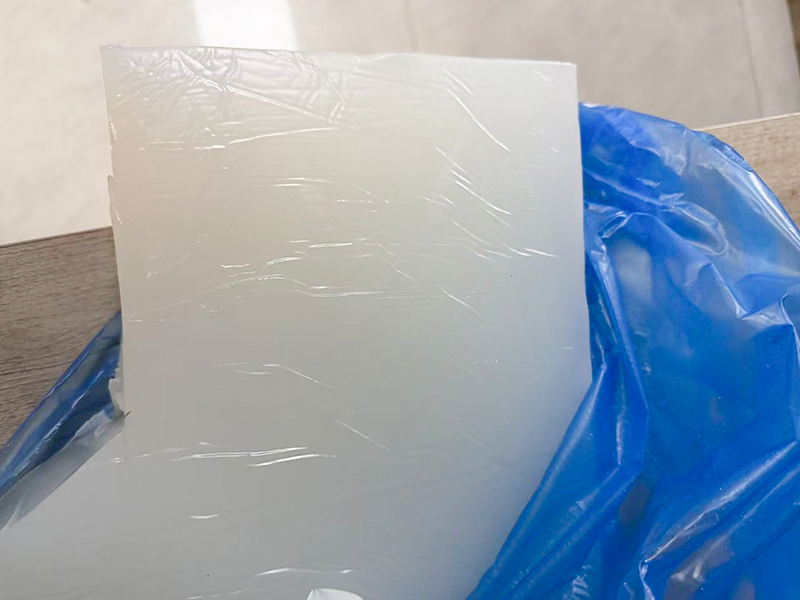
Are You Interested?
Are You Interested?


Content
Every electric vehicle depends on a network of conductors that move hundreds of amps between the battery pack, the traction inverter, the onboard charger, and the drive motor. These conductors operate at system voltages that now commonly reach 400V, with a growing share of new platforms moving toward 800V architecture to support faster charging and lighter cabling. At these voltage levels, the insulation surrounding the copper or aluminum conductor is not a minor component of the wiring harness. It is the primary safety barrier standing between a live conductor and the vehicle occupants, the chassis, and every technician who will ever service the car.
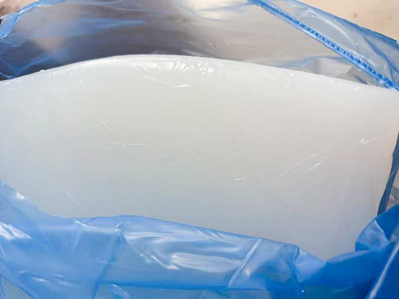
Automotive High Voltage Cable Silicone Rubber has become the dominant insulation choice for this application because it satisfies a demanding combination of requirements that few polymer families can match simultaneously: high dielectric strength, wide thermal operating range, chemical resistance to coolant and lubricant contact, and long-term flexibility in a vehicle that will flex, vibrate, and thermally cycle for over a decade.
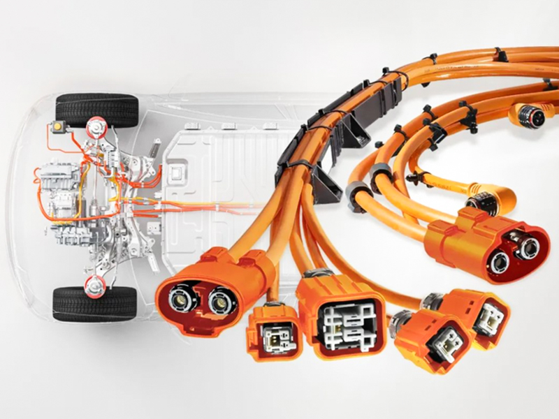
This article examines the material science and engineering reasoning behind that adoption, using measurable performance criteria rather than marketing language, so that engineers evaluating cable insulation for a new EV platform can understand exactly what silicone rubber contributes at each stage of the design and validation process.
Dielectric breakdown strength describes the electric field a material can withstand before it fails and allows current to pass through the insulation wall. For a cable rated at 800V system voltage with realistic transient spikes during regenerative braking or fast charging, the insulation must retain a wide safety margin above the nominal operating voltage across its entire service life, not just when it leaves the factory.
Silicone rubber compounds formulated for automotive high voltage cable applications typically demonstrate breakdown strength in the range of 20 to 25 kilovolts per millimeter at room temperature, a figure that degrades far less with temperature and aging than general purpose rubber or standard thermoplastic jacketing. The chart below summarizes typical dielectric performance across four common insulation material families used in automotive wiring, based on aggregated industry test data at comparable wall thickness.
The margin matters most at the extremes of the operating envelope. When temperature rises toward 150 degrees Celsius near a busbar connection point, dielectric strength in lower grade compounds drops sharply, while silicone rubber insulation retains a much larger fraction of its room temperature rating, preserving the safety margin exactly where the cable is under the most electrical and thermal stress at once.
An EV high voltage cable does not experience a single steady temperature. It sees ambient cold in winter climates, radiant heat from a battery pack or inverter housing, resistive self-heating under sustained fast charging current, and short duration thermal spikes near power electronics. Silicone Rubber HV Cable for NEV Battery Electric Vehicles is specified in large part because its polymer backbone remains chemically stable and mechanically sound across an unusually wide continuous operating range, commonly rated from minus 60 degrees Celsius up to 200 degrees Celsius depending on the specific compound and cure system.
The line chart below illustrates how insulation resistance, expressed as a percentage of its baseline room temperature value, changes as ambient and conductor temperature rise from minus 40 to 200 degrees Celsius. Maintaining insulation resistance under heat is what prevents leakage current from creeping upward and tripping isolation monitoring systems that every EV relies on for occupant safety.
The gap widens above 100 degrees Celsius, which is precisely the zone where fast charging events and dense pack layouts push local cable temperature. A cable that keeps its insulation resistance high under these conditions gives the vehicle's isolation monitoring circuit a stable, trustworthy signal instead of a noisy one that can trigger unnecessary fault codes or, worse, mask a genuine developing fault.
Voltage rating and thermal endurance only matter if the cable also survives the physical environment of a vehicle. High voltage cables route through wheel wells, engine bays now shared with drive units, and chassis members that flex under suspension travel and torsional loads. A cable that becomes stiff and brittle in cold weather risks jacket cracking during routine service or a hard winter start, while a cable that softens excessively in heat risks abrasion damage against nearby brackets.
The column chart below compares tensile elongation retention after accelerated thermal aging equivalent to roughly 3000 hours at 150 degrees Celsius, a common qualification benchmark referenced in automotive cable specifications. Elongation retention indicates how much stretch capability, and therefore flexibility, a jacket material keeps after long term heat exposure.
Below is a practical summary of cold and hot flexibility behavior relevant to routing decisions during harness design.
| Condition | Silicone Rubber Jacket | Typical Thermoplastic Jacket |
|---|---|---|
| Cold bend at minus 40 C | Remains pliable, no cracking | Stiffens, cracking risk rises |
| Continuous flex near 150 C | Retains rubber-like elasticity | Softens, deformation risk |
| Minimum bend radius behavior | Stable across service life | Tightens with age, less forgiving |
| Vibration fatigue resistance | High, due to elastomeric recovery | Moderate, depends on formulation |
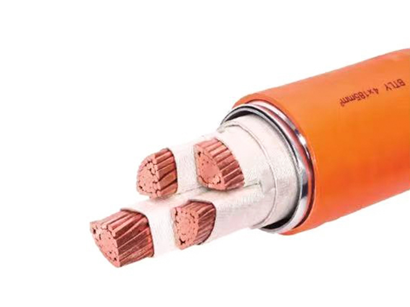
High voltage EV cables carry switching currents generated by the traction inverter, and that switching activity radiates electromagnetic interference that can disrupt low voltage control circuits, sensors, and infotainment systems if left unmanaged. An EMI shielded Silicone Rubber Automotive Cable pairs a braided or foil shield layer with the silicone insulation and jacket system so the shield can carry away induced currents while the surrounding rubber maintains the flexibility and thermal performance the rest of the harness depends on.
The shield itself is normally a tinned copper braid providing coverage in the range of 85 to 95 percent, terminated to chassis ground through a low impedance connection at both cable ends. Silicone jacketing is compatible with this construction because it does not degrade or become brittle where it contacts the braid over years of thermal cycling, unlike some thermoplastic jackets that can craze at the shield interface after repeated expansion and contraction.
Shielding effectiveness is typically validated across a frequency sweep from roughly 10 kHz through 1 GHz, since inverter switching harmonics and coupled noise can appear across a wide spectrum. A cable construction that maintains mechanical integrity of the shield layer under real-world flexing directly protects the attenuation performance measured in that sweep.
No single number captures why silicone rubber is selected over alternative insulation families. The decision is a balance across several performance axes at once. The radar chart below plots five attributes on a common relative scale, comparing a typical automotive silicone rubber compound against a general purpose rubber compound used in less demanding wiring applications.
The visual gap is largest on thermal stability and aging resistance, which lines up with real world failure data collected during long duration vehicle testing, where insulation breakdown near hot components is a leading cause of high voltage cable field returns for compounds not designed for automotive severity levels.
Understanding the build sequence helps explain why silicone rubber cable assemblies achieve consistent quality once the material choice is made correctly. The flowchart below outlines the general process from conductor preparation through final validation before a cable assembly is released for vehicle integration.
Each stage carries its own inspection checkpoint. Insulation wall thickness and concentricity are measured continuously during extrusion, shield coverage percentage is sampled per production lot, and finished assemblies undergo dielectric withstand testing, insulation resistance measurement, and thermal cycling before release. Because silicone rubber processes consistently through high speed extrusion lines, wall thickness variation can be held tighter than with some general purpose rubber compounds, which directly supports dielectric performance repeatability across a full production run.
Cable qualification for EV high voltage circuits is not judged against a single document. Engineering teams typically reference a combination of international and regional standards covering insulation, connector interfaces, and system level isolation requirements. The table below summarizes commonly referenced standards and the aspect of performance each one governs.
| Standard Reference | Primary Focus |
|---|---|
| ISO 6722 | Low voltage single core cable requirements, used as a comparative baseline |
| ISO 19642 | Road vehicle cable sets, including high voltage cable requirements |
| USCAR-37 | Performance specification for automotive electrical wiring assemblies |
| GB/T 34513 | High voltage cable assembly requirements for new energy vehicles |
| LV 216 | Regional OEM specification for high voltage cable systems |
Automotive High Voltage Cable Silicone Rubber constructions are formulated specifically to meet the flame resistance, dielectric withstand, and thermal endurance clauses common across these documents, which is one reason the material has become a default starting point for new EV platform cable specifications rather than a specialty option evaluated only for extreme applications.
Compliance testing typically includes flame propagation testing on bundled harness samples, fluid resistance testing against coolant and battery electrolyte simulants, and low temperature impact testing to confirm the jacket does not crack under mechanical shock at cold soak conditions. Silicone compounds formulated for this duty generally pass these tests with margin, though the exact cure system and filler package used by a given compound still need to be validated against the specific standard version an OEM program references, since revisions do periodically tighten pass thresholds.
Not every high voltage run in a vehicle sees the same stress profile, and harness engineers generally prioritize silicone rubber cable in the zones where thermal and mechanical severity is highest, while sometimes accepting a lower cost alternative in more benign, protected routing paths.
A cable routed within close proximity to a drive unit or a DC fast charging inlet experiences a materially different thermal and vibration profile than one routed along a protected chassis rail, and insulation selection should reflect that difference rather than applying one specification uniformly across the entire harness.
Standardizing on one insulation family across most or all high voltage branches also simplifies harness manufacturing, reduces the number of unique bend radius and clamping specifications a production line must manage, and lowers the risk of a mismatched material being installed in a high severity location during a design revision.
Automotive grade silicone rubber compounds are commonly rated for continuous operation from around minus 60 degrees Celsius up to 200 degrees Celsius, depending on the specific formulation and cure system, with short duration excursions tolerated beyond that range in some compounds.
Conductor size determines current carrying capacity and resistive heating, but it is the insulation's dielectric strength that prevents the electric field around a high voltage conductor from breaking through to a person or the chassis, making it the primary safety barrier regardless of how the conductor itself is sized.
Yes, in a beneficial direction. Silicone rubber retains elastomeric flexibility across a much wider temperature range than rigid thermoplastic jackets, which reduces cracking risk in cold climates and stiffness related routing constraints in hot zones near the drivetrain.
A braided or foil shield layer is applied over the silicone primary insulation and then covered by the outer silicone jacket, with the shield terminated to chassis ground at both ends through the connector system to carry away induced interference currents.
Programs frequently reference a combination of ISO 19642, USCAR-37, GB/T 34513, and applicable regional OEM specifications, each covering different aspects of dielectric, thermal, mechanical, and flame performance for the finished cable assembly.

What to stay up to date?
Contact us via the email address below.
No. 16, Industrial Concentration Zone, Daibu Town, Liyang City, China
Copyright 2026 Liyang Tiansheng Insulating Materials Co., Ltd. All Rights Reserved.
Custom Insulation Material For Cable Industry Suppliers

